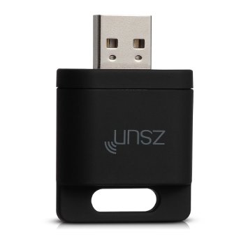
I’ve been interested for the crypto world for a few months now and I’ve acquired a ming rig, otherwise I wouldn’t feel complete 🙂

For all of you that have a mining rig, you’re probably familiarised with those tiny usb devices that you stick in a usb port to monitor your computer and reset it in case it hangs/freezes.


This is known as a usb watchdog and the way it works is very simple:


  1. Connect this device to a USB port. The usb watchdog has 4 pins: 2 that should be connected to the power switch and another 2 for the reset button. Use jumper wires to make the connection.
  2. When the watchdog gets powered on, it will wait for x amount of time for you to tell him “Hey, I’m still a alive! Wait for x more seconds and if you don’t get back from me again then please reset the computer”.
  3. Repeat the previous step indefinitely

Those messages are sent by a specific software. If for some reason your computer crashes,  then the watchdog won’t receive another message from the software. If a message is not sent within those x seconds, the usb watchdog will know that something isn’t right and it will issue a hardware reset simulating the physical push of the reset button.


This usb watchdogs are shipped with dedicated software, which in my case is pretty useless because it was made for Windows computers and my mining rig is linux based. I could try to use wine but I don’t feel like killing flies with bazookas.


The windows software seemed pretty basic how hard could it be to reverse engineer the protocol?


Couldn’t be easier:

The first thing was to find some software that could inspect the connection and check what was being passed back and fourth. The first link provided by google was all I needed. I’m talking about this one.


Using a Serial port sniffer it was pretty obvious to understand the patterns.  First let’s check the serial port settings:

  • Baud rate: 9600
  • Parity bits: None
  • Stop bits: 1

This is enough for you to start sending messages to the usb watchdog.

The protocol:

The only thing that you need to know now is the protocol. The sniffer will give you a good picture of it.
First of all, whenever you open the watchdog software, you can see that it sends a packet (0x80) which then get an answer from the watchdog (0x81). I’m not entirely sure of how data is encoded but it’s pretty clear that whenever the software connects, it presents you with a message containing the firmware version. I would say that this is probably encoded here in this byte.

Then you can see a sequence of bytes (0x10) that are being sent at a rate of 1/s. The timeout value was set to 160 seconds. If I set the timeout value to 10 seconds, the application will start sending 0x01.

So, if 1 equals to 10 seconds, 160 seconds should be equal to 16. What is the hexadecimal representation of 16? You guessed it: 0x10 🙂

If click on the reset button, a 0xff is sent and the relays are triggered.

As far as I know, there are only these three operations available:

  • Reset
  • Send a heartbeat with the current timeout value.
  • Check firmware version


The script


If you were expecting something fancy, you’ll be disappointed, but the sources are available here: https://github.com/zatarra/usb-watchdog 🙂
Basic functionality is implemented but you might want to extend it. You can test your video cards, test an internet endpoint, or you could even remote restart your mining rig.  Use your imagination! 😀


Warning: Do not set the heartbeat interval to a very low value, such as a minute. If you do that and your computer crashes,  you will have one minute to complete the boot process and load this script. If your computer fails to do that it will get stuck in an infinite loop which sucks if your mining rig is in a remote location.


Check my repository for the latest version of this script.


If you find this useful, buy me a beer: 😀

bitcoin: 3Mj3v5hrx5qQhwzzWPMGwkJ8DRMCywhZFy
bitcoin cash: 1KDbjLM9DdsCyfDMSYHdm52r5R3BRP2dfS
ethereum: 0xfF7167e9ea8A4d882dd9161FC5F1560B9031A6c6
litecoin: MERSbMVM9NmQoDhr5ktswpaumWk8dGbyUu
ripple: rN1sXzZUBej2wiZSjgKtAgNRTUoFhUdt36 
stellar: GBYS4JGPYZI774ZIU3KNEKSDUK2E3VMXQO4AZTHAO7WU4EZRSG7QF5MG


For those of you that are into digital currency and have been following Monero, you probably know by now that an ingenious web based miner was created, allowing people to monetize websites by using some cpu cycles from their visitors.

Unfortunately this has been used in malicious ways ( e.g. here and here ) which pushed it to several Anti Virus’s blacklists or popup blockers.

Since then, the original developers tried to create a alternatives to clear CoinHive’s image, but at this point it might be complicated to revert all the actions that were set in place to stop its usage as malware.

For now, you might be better off running your own cluster ( to avoid issues with anti virus or adbockers ) and to do that you need to use a middleware that translate’s coinhive’s custom protocol to something that most of the mining pools can understand: stratum protocol.

That’s where this neat tool enters. CoinHive Mining Stratum Proxy is a Python tool that can act as a proxy between your website clients and a mining pool. This is particularly important since coinhive.com is blocked by several security tools.


The original tool was already a great tool, but I’ve decided to add SSL support and make the command line more clear regarding to the accepted parameters. Another nice feature the ability to check how many clients are currently connected and how many hashes were accepted.

Feel free to check out my version here https://github.com/zatarra/coinhive-stratum-mining-proxy and the original version here. I’ll open a pull request to the original project once I complete the tests for these new features that I’ve added.

A couple of weeks ago a friend introduced me to a dirt cheap wifi enabled mains switch. I’ve been creating my own wifi switches for a few years now but at $5 it is not worth it anymore for me to spend time adding electronic modules to make one.

The original device comes loaded with a firmware that can be used with a specific piece of software.  Now  I don’t know about you, but I rather run my own stack of software on it because I do have some trust issues, specially when I have no idea who’s behind the software development.


Fortunately there are several tutorials that you can explain everything you need to know to upload a custom firmware. This was the one that I used. TL;DR: solder a 5 pin 0.1in header to access the UART port and use one of those usb->uart converters.


My requirements were pretty simple: A tiny webserver should be up and running  ( connecting to my home network ) exposing two or three endpoints ( enable, disable, status ). This is the result:


#include <ESP8266WiFi.h>
#include <WiFiClient.h>
#include <ESP8266WebServer.h>
#include <ESP8266mDNS.h>
 
const char* ssid = ".....";
const char* password = ".....";
 
ESP8266WebServer server(80);
 
const int led = 13;
bool relayOn = false;
 
void handleRoot() {
  digitalWrite(led, 1);
  server.send(200, "text/plain", "hello from Sonoff\nRelay status:" + ( relayOn ? String("ON") : String("OFF") ) );
  digitalWrite(led, 0);
}
 
void handleNotFound() {
  digitalWrite(led, 1);
  String message = "File Not Found\n\n";
  message += "URI: ";
  message += server.uri();
  message += "\nMethod: ";
  message += (server.method() == HTTP_GET) ? "GET" : "POST";
  message += "\nArguments: ";
  message += server.args();
  message += "\n";
  for (uint8_t i = 0; i < server.args(); i++) {
    message += " " + server.argName(i) + ": " + server.arg(i) + "\n";
  }
  server.send(404, "text/plain", message);
  digitalWrite(led, 0);
}
 
void setup(void) {
  pinMode(led, OUTPUT);
  pinMode(12, OUTPUT);
  digitalWrite(led, 0);
  Serial.begin(115200);
  WiFi.begin(ssid, password);
  Serial.println("");
 
  // Wait for connection
  while (WiFi.status() != WL_CONNECTED) {
    delay(500);
    Serial.print(".");
  }
  Serial.println("");
  Serial.print("Connected to ");
  Serial.println(ssid);
  Serial.print("IP address: ");
  Serial.println(WiFi.localIP());
 
  if (MDNS.begin("esp8266")) {
    Serial.println("MDNS responder started");
  }
 
  server.on("/", handleRoot);
  server.on("/enable", []() {
    turnOn();
    server.send(200, "text/plain", "Relay enabled");
  });
  server.on("/disable", []() {
    turnOff();
    server.send(200, "text/plain", "Relay disabled");
  });
  server.on("/toggle", []() {
    toggleRelay();
    if ( relayOn )
      server.send(200, "text/plain", "Relay enabled");
    else
      server.send(200, "text/plain", "Relay disabled");
  });
 
  server.onNotFound(handleNotFound);
 
  server.begin();
  Serial.println("HTTP server started");
}
 
void loop(void) {
  server.handleClient();
}
 
void turnOn() {
  digitalWrite(12, HIGH);
  relayOn = true;
}
 
void turnOff() {
  digitalWrite(12, LOW);
  relayOn = false;
}
 
void toggleRelay() {
  if ( relayOn ) {
    digitalWrite(12, LOW);
    relayOn = false;
  }  else {
    digitalWrite(12, HIGH);
    relayOn = true;
  }
}


There’s a GPIO pin that you can use for things like 1wire protocol devices ( e.g. ds18b20 temperature sensor, or a DHT22/11 ). I’m planing to add that to this simple sketch. In the meantime feel free to check out the repository . All of the updated will be there.


PS: Yes, I know the code is ugly, but that was not the point. Feel free to change it and improve it!

Today I’m going to show you something different.

Qwertee the popular tshirt markeplace is on sale with prices as low as 4 euros.  The thing is, it is very annoying to check their prices since they force you to hover each and every tshirt image to reveal the price.

Checking the DOM it was pretty clear what needed to be done to see all the prices at once. So I thought to myself, why not do it in an easy way that more people can enjoy it?

And that’s how I created a tiny chrome extension to check the prices.

screen-shot-2016-10-01-at-16-27-14


How does it work?

The workflow is pretty simple:

  1. Use javascript to create a new <style> element.
  2. Add three rules to override the display mode of three classes ( price, hover-info and product-price )
  3. Inject the new style element into <head>


Feel free to check out the code on github and perhaps improve it. It’s free and open source! 🙂

A friend of mine told me that he was going to do a presentation about the famous Rubber Ducky.

For those of you who don’t know, rubber ducky is a USB dongle that emulates a keyboard disguised of flash drive.

rubber-ducky

Obviously, this is the perfect solution for a social engineering experiment, but at 44USD it is a bit pricey given that there are a few other devices that can perform in a similar way for less than 1/4 of the price.

Today I’m going to talk about one of those alternatives: The Arduino Beetle.

arduino-beetle

The arduino beetle is a tiny solution based on the ATMEGA32U4 the same micro controller that you can find in the Arduino Leonardo. It does support USB without any external components which makes it a very good option to build these minified dongles.


For this reason, creating arduino sketches that emulate a keyboard is quite trivial. In fact, it is so easy that it makes this tool look a bit worthless. Nevertheless, I’ve decided to create a small tool that would allow you to convert and use the existing Rubber Ducky Payloads with this little device.


How to Use it?

  1. Pick a payload you like and save it to a file. For instance this one: https://github.com/hak5darren/USB-Rubber-Ducky/wiki/Payload—osx-youtube-blaster
  2. Call rubberduino-convert and pass the payload file as the first argument. Pipe the output to a new file.
  3. Open your favourite arduino IDE and paste the contents of the file previously created.
  4. Upload the sketch to your arduino leonardo/beetle
  5. Enjoy 🙂


Issues

This is a very alpha version the code is not polished at all. Even though it does work pretty well there are a few issues:

  • Symbol handling – Special symbols will depend on the keyboard layout that you’re using. Currently it is working with portuguese layouts but it needs to be adjusted in case you have a different one. The way I did it was to run a test sketch that would show you the output of each char mapped between 1 and 100. I then picked them and created a dictionary called symbol_ids inside the python module to map the char. ( e.g. {“/”: 39, “ç”: 11, “&”:24 } and so on ).
  • The sketches are loooooongBecause of the issue mentioned above, I have to rely on keyboard.write to send a char at the time. This can make the sketches look big and makes it uncomfortable to troubleshoot but it was the easiest way for me to do it. Feel free to improve it. This was improved by 15% ( the size of the compiled sketch ).
  • Delay handling – The payloads can be produced either by using a default DELAY command that will stay between actions or by explicitly adding them to the code. Currently I always add a DELAY command between the actions which means that I might be introducing more delays than I should ( e.g. the payload you provided already has them ).

Feel free to check out the code here: https://github.com/zatarra/rubberduino

You can get the Beetle for less than $6 on Aliexpress ( thanks deine0ma! )

PS: You can follow an interesting discussion on reddit

I love to travel.

Because of this, I can spend lots of time searching for the best deal I can find on a given destination. Fortunately there are several web ninjas that simplify this hard task for you. Some of these ninjas, are the guys from Fly4Free.

Checking on their website on a regular basis is quite trivial and they do have everything categorized, but I wanted to take it one step further to the ultimate lazy level 🙂

Actually, I was also looking for an excuse to learn how to create Chrome extensions and this sounded like the perfect one.


Screen Shot 2016-09-14 at 12.12.03

The workflow is pretty simple:

a) Download the RSS feed.

b) Look for interesting keywords ( you can customize which ones ) such as destinations.

c) Create a notification with this information.

d) Store the current information for later presentation.


The chrome extension is open source, so feel free to improve it or just check it out either on the chrome store or on github

The Micropython binaries for ESP8266 got released last week and I decided to give it a try. As an “Hello World” application, I wanted to try the wireless capabilities and control a few relays. Nothing fancy, but I was just for testing purposes.


Without further due, this is the snippet of code that I used to bring a HTTP servers that was capable of reading GET variables and parse the PATH:


import machine
import socket
import ure
 
RELAYS = [machine.Pin(i, machine.Pin.OUT) for i in (12, 13, 14, 15)]
 
def getPinStatus():
  return RELAYS
 
def setPin(pin, value):
  RELAYS[int(pin)].value(int(value))  
  return "PIN %s set to %s" % (pin, value)
 
def parseURL(url):
  #PARSE THE URL AND RETURN THE PATH AND GET PARAMETERS
  parameters = {}
 
  path = ure.search("(.*?)(\?|$)", url) 
 
  while True:
    vars = ure.search("(([a-z0-9]+)=([a-z0-8.]*))&amp;amp;?", url)
    if vars:
      parameters[vars.group(2)] = vars.group(3)
      url = url.replace(vars.group(0), '')
    else:
      break
 
  return path.group(1), parameters
 
def buildResponse(response):
  # BUILD DE HTTP RESPONSE HEADERS
  return '''HTTP/1.0 200 OK\r\nContent-type: text/html\r\nContent-length: %d\r\n\r\n%s''' % (len(response), response)
 
addr = socket.getaddrinfo('0.0.0.0', 80)[0][-1]
 
s = socket.socket()
s.bind(addr)
s.listen(1)
 
print('listening on', addr)
 
while True:
    cl, addr = s.accept()
    print('client connected from', addr)
    request = str(cl.recv(1024))
    print("REQUEST: ", request)
 
    obj = ure.search("GET (.*?) HTTP\/1\.1", request)
 
 
    if not obj:
      cl.send(buildResponse("INVALID REQUEST"))
    else:
      path, parameters = parseURL(obj.group(1))
      if path.startswith("/getPinStatus"):
        cl.send(buildResponse("RELAY STATUS:\n%s" % "\n".join([str(x.value()) for x in getPinStatus()])))
 
      elif path.startswith("/setPinStatus"):
        pin = parameters.get("pin", None)
        value= parameters.get("value", None)
 
        cl.send(buildResponse("SET RELAY:\n%s" % setPin(pin, value)))
      else:
        cl.send(buildResponse("UNREGISTERED ACTION\r\nPATH: %s\r\nPARAMETERS: %s" % (path, parameters)))
 
    cl.close()


You can get the gist here


The code will give you two different endpoints:

  • /getPinStatus -> Check if the relays are on or off
  • /setPinStatus -> Enable/disable pins. you need to pass a pin number (0 to 3) and a state (0 to disable, 1 to enable the relay). E.g. http://192.168.4.1/setPinStatus?pin=0&value=1

The code is not pretty, and probably full of bugs, but the basic functionality is there.  All you have to do is to connect to a Wifi network ( or create your own access point), add the relays to GPIO 12, 13, 14 and 15 and you’re done. You have plenty of other tutorials to teach you how to connect things to your esp8266.

The code was based on the official example that you can find here


As always, feel free to suggest improvements 🙂


EDIT: Thank you Chris for identifying an issue with the regular expression!

This is going to be a quick one.

Remember ZSUN Wifi Card reader? It seems that there’s a new device that does the same thing. In fact it does look like a clone:


EAGET


I just bought one of these from a Chinese supplier. It costed $7.5 USD and it does exactly the same. Using NMAP to scan for open ports I get the same results. So it was not surprising when I got access to it using the very same password “zsun1188”.

Screen Shot 2016-04-21 at 20.40.08


In order for you to flash the existing firmware you need to edit /etc/producttype and replace the A50 for SD100.  The rest of the process should be pretty straight forward.


Enjoy your dirt cheap new router 🙂

Today I decided to buy a mechanical keyboard. I was looking for a minimalist TKL and the one I picked was an Ozone Strike Battle with brown cherry mx switches. What I wasn’t counting on is the crappy support provided by a vendor that could render useless a simple device just like a keyboard.


The first time I plugged the keyboard in my macbook, the keys were completely messed up. And I’m not talking about the symbols or special keys. Several keys were bound to the same value and some others didn’t even have a valued assigned.  After spending a few minutes googling, I found a thread that gave me the first hint about what was happening. Unfortunately this didn’t work for me and it took me some time to understand why. It seems that newer keyboards have different ids which are not configured. The solution was to clone the repository found in the previous link, use their tool to detect the bcdDevice, add it to the config and compile the kernel extension.


I’m not an expert and it took me a couple of hours to do so because I couldn’t find the right sources for one of the dependencies that are required – IOKit – but once I did it, everything worked as expected and right now I’m writing this post using my new mechanical keyboard 🙂


good meme


Step by Step: How to make it work for you?

  • Navigate to the link mentioned above and download the kernel extension mentioned there ( or use this direct link )
  • Try to installed it. If you’re using El Capitan, you’ll have to disable System Integrity protection to load the kernel extension. Try the following:
    1. Reboot your computer and press cmd + R during boot to enter recovery mode.
    2. Open a console and type csrutil disable; reboot. This will allow you to use kernel extensions that were not signed by Apple.
  • If you are running a previous version of OSX, then you can just do sudo nvram boot-args=kext-dev-mode=1
  • Load the extension: kextutil -v /System/Library/Extensions/IOUSBHIDDriverDescriptorOverride.kext
  • Plug in the keyboard. If your keyboard is now responding correctly then everything is OK. If not, you might have one of the new versions that have a different bcdDevice.  You can download this custom version  of the kernel extension that I compiled and see if it works for you: http://davidgouveia.net/goodies/IOUSBHIDDriverDescriptorOverride.kext.tar.gz

If you want to compile it by yourself, make sure you have xcode installed and ruby 2.2.0.

brew install libusb
bundle install --without ""

rake scan
  • Check the idVendor, idProduct, and bcdDevice. Open the Info.plist file, locate the blocks of code related to the strike battle keyboard ( just search for “strike” ). Change those blocks of code to match the idVendor, idProduct, and bcdDevice values that you found using the previous command.

Screen Shot 2016-03-27 at 12.52.16

  • Compile the code using the instructions that you can find on the repository’s README.md:
# dependencies
gem install bundler
bundle install --without scan

# build
xcodebuild
sudo cp -r build/Release/IOUSBHIDDriverDescriptorOverride.kext \
    /System/Library/Extensions
sudo kextutil \
    /System/Library/Extensions/IOUSBHIDDriverDescriptorOverride.kext

This is it, you should now have a working kernel extension that suits your needs. Enjoy your new keyboard 🙂

I was one of the guys that got the Zsun fever 🙂

I’m not going to get into details. For those you can check the Warsaw Hackerspace’s website. Those guys did an awesome job compiling information related to this tiny yet powerful device.

Originally it comes with a custom firmware that provides you with an access point that can be used to share files ( it has a microsd slot ). By flashing OpenWRT it allows you to unleash all it power and use it to several different things (access point, range extender, file server using different protocols, IoT, Tor server,  you name it), but since you can only access it via wifi ( there’s a physical ethernet port that you can use if you don’t mind tearing apart the case and solder an ethernet jack)  it can be very easy to lose access to the devices.

I’ve seen some people talking about a trick using the sd card slot during boot to force a software reset but it didn’t work for me, so I just decided to do something different.


The approach is easy. Create a script  that is loaded on boot and checks for a file on the memory card. If it’s there, then it issues a firstboot command to reset everything. This is similar to the update process of several gadgets and it’s easy to implement.


1º Flash the OpenWRT firmware ( check the hackerspace link )

2º Open the web interface. Enable the SD card automount feature and mount it on /mnt/sda1 (this should be the default). Enable enable SSH.

3º Log on using SSH. Create a file called restore inside /etc/init.d/ and dump the following contents there:


#!/bin/sh /etc/rc.common
# Copyright (C) 2009-2012 OpenWrt.org
 
START=50
 
start() {
  if [ -f "/mnt/sda1/restore" ]
  then
    echo "y" | /sbin/firstboot
    rm /mnt/sda1/restore
    /sbin/reboot
    echo "Rebooting to apply changes"
  fi
}
 
stop() {
  echo "Stop action not used."
}
 
reload() {
  echo "Reload action not used."
}
 
shutdown() {
  echo "Shutdown action not used."
}


4º Save the file and change the permissions to 755 ( chmod 0755 /etc/init.d/restore )

5º Enable the script on boot. To do so execute the following command: /etc/init.d/restore enable

And that’s it. If for any reason you mess up the wireless interface and lose access to the device, all you have to do is create a blank file inside the SD card called restore and the next time you boot the device it will detect this and force the reset.

Warsaw Hackerspace: https://wiki.hackerspace.pl/projects:zsun-wifi-card-reader